Marconi Eras
MARCONI TRANOCEANIC RADIO TELEGRAPHYPractical Wireless Telegraphy
for STUDENTS of
RADIO COMMUNICATIONS
by ELMER E. BUCHER
Instructing Engineer
Marconi Wireless Telegraph Co. of America
Page 292-293 (1917-1920 edition) 294+ (1917 edition)
Webeditor: This post was taken from photocopies Mr. William Brahms made from the original book while researching the history of Franklin Township. The New Brunswick Station lies in Franklin Township. The account is a contemporary description of the stations and how they worked as a pair with counterparts in Wales. Thanks to Mr. James Stewart we have pages 294-307 and other parts of the book from the 1917 edition…
“The receiving aerial for this station at Belmar, New Jersey, consists of two wires 6,000 feet in length, suspended on six tubular masts, 400 feet in height.”
On page 296 is a description of the equipment at Belmar…
“The receiving station at Belmar, New Jersey is completely equipped with a Marconi balanced crystal receiving set, Brown amplifying relays, a balancing out aerial for eliminating interference, dictaphone receivers, and a set of telegraphic instruments for connection with the landline telegraph and telephone companies. These transmitting and receiving stations not only have the necessary buildings for the housing of the apparatus, but hotels and individual dwellings are supplied for the employees as well.”
Also on page 299 there is a description with photos of the erection of the 400 Foot Belmar wireless masts.
292 PRACTICAL WIRELESS TELEGRAPHY
233. Marconi Directional Aerial.-The great success of Signor Marconi’s Trans-oceanic system is in no small measure due to the use of the horizontal directional aerial.* Fully convinced by a series of quantitative experiments that the flat top aerials radiate more freely in the direction opposite to which the free endpoints, particularly if the length of the flat top exceeds the length of the vertical portion by four or five times, Signor Marconi decided that the adoption of this aerial would not only permit the transmission of messages over great distances with small powers but also on account of its directional properties would prevent a considerable amount of interference to the operation of other stations.
In the same series of experiments, it was determined that a flat top aerial receives with greater intensity when the free endpoints in the direction opposite to the free end of the transmitter aerial. Irrespective of its selective directional properties, a horizontal aerial of given capacity and inductance for any required wavelength, is less expensive to erect than a vertical aerial of similar electrical dimensions; hence, from this consideration alone, the flat top aerial is the one that would be adopted.
In order to radiate the energy of a 300 K. W. transmitter, the aerial should have a fundamental wavelength of at least 6,000 meters; in fact the greatest distances are covered when such aerials radiate near to their fundamental wavelength.
The great Marconi station at New Brunswick, New Jersey, U. S. A., for example, has an aerial of 32 wires connected in parallel, 5,000 feet in length. The aerial is supported by 12 tubular steel masts, 400 feet in .height, arranged in two rows of six each. The fundamental wavelength is approximately 8,000 meters, but the initial transmitting experiments were carried on at the wavelength of 15,000 meters.
The receiving aerial for this station at Belmar, New Jersey, consists of two wires 6,000 feet in length, suspended on six tubular masts, 400 feet in height. The aerial has a general direction favorable for reception from the giant transmitting station at Carnarvon, Wales.
234. Marconi Transoceanic Stations.-By far the greater number of high power radio stations here and abroad have been designed and erected by the*An explanation of the cause of the unsymmetrical radiation of an inverted L aerial appears in Page 167 of Fleming’s Elementary Manual of Radio Telegraphy.
MARCONI TRANOCEANIC RADIO TELEGRAPHY 293Marconi Company. In fact, their stations only have maintained a continuous operating schedule from day to day, from continent to continent. Individual concerns may have carried out spectacular experiments here and there, but nothing has been evolved by them that would tend to make long-distance communication a success commercially. The mere fact that a message may, for instance, be sent across the ocean by a low-powered transmitter and received on a small aerial at certain hours of the day is no indication that such equipment could be used for continuous 24-hour service because experiment reveals that very large powers are required for continuous operation when the sender and receiver are 3,000 miles apart.
Those who are familiar with the great globe-girdling scheme of the Marconi Company cannot help but be impressed with the stupendous undertaking involved in the construction of their high power stations, for not only is the task of designing the apparatus, buildings, and power machine.-y one of the extraordinary undertaking, but the actual installation of such has, in many instances, called for painstaking labors and effort largely due to the location, the nature of the soil, and the topography of the surrounding country.
In view of the universal interest manifested by students of radio in behalf of high power radio stations of the Marconi Company, a brief description of their equipment will be presented, together with such additional information, as will make clear the general plan and mode of operation. First let it be explained that although these stations could all be made intercommunicating, it is more usual to construct a pair of stations to cover a specific route or to join together two continents only.
With the idea in view of showing which of these stations was intended for communication with the other, they shall be grouped into “radio circuits” or routes, as follows
| Stations separated about 30 miles |
Stations
separated about 12 miles |
Since the apparatus for the Glace Bay station has been very briefly described in paragraphs 274 and 275, it will not be gone over again, except to mention that the Duplex System has been installed and thoroughly tested. Because these two stations established the first successful trans-oceanic commercial radio service, they are purposely grouped at the head of the list.
| Stations separated about 50 miles |
Stations
separated about 62 miles |
The transmitting station at New Brunswick is of 300 K. W. capacity and can be operated at various wavelengths from 7,000 to 15,000 meters. Power is taken in the station from a commercial powerhouse at 1,100 volts, 3 phase 60 cycle alternating current, stepped down to 440 volts, and led to the terminals of a 60 cycle, 440-volt 3 phase 550 H. P. motor, which drives a 300 K. W. 120 cycle generator.
The current is led from the generators to a bank of high voltage transformers, the secondaries of which may be connected in series or in parallel according to the power required.
In the usual manner, the current from these transformers charges a large bank of high voltage oil plate condensers which, in turn, discharge through an oscillation transformer and rotary disc discharger of uncommon proportions. As in the Glace Bay Station, the circuit from the transformer secondaries to the condenser is interrupted by a specially designed set of high tension relay keys which, in turn, are actuated by a small sending key and a source of direct current.
Arcing at the contacts of the main signaling key is prevented by a heavy blast of air forced directly at the contact points by specially designed motor blowers. The advantages
294 PRACTICAL WIRELESS TELEGRAPHYderived in interrupting of the high voltage current, lies in that it permits 300 K.W. to be handled at various speeds of transmission up to 100 words per minute without error.
A more detailed description of certain apparatus of the circuits of radio frequency for the New Brunswick station and others with like equipment (damped wave apparatus) will be given in paragraph 236.
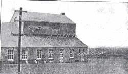
Fig 303 – Power House of the Trans-Atlantic Marconi Station at Carnarvon, Wales.
The transmitting aerial at the New Brunswick station is of the inverted L type, consisting of 32 wires with a flat top approximately 5,000 feet in length. It is supported on two rows of steel tubular masts (6 masts in each row), which are approximately 400 feet in height. The two rows of masts are separated about 250 feet in length.
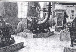
Fig 304 – Motor Blowers at Carnarvon Station.
The transmitter at Carnarvon, Wales is substantially a duplicate of the New Brunswick transmitter, the source of power being a 300 K. W., 150 cycle motor-generator
MARCONI TRANOCEANIC RADIO TELEGRAPHY 295
with step-up transformers, oil condensers, etc. Of late, a 150 K.W. timed spark discharger, excited by 5,000 volts continuous current, has been employed as well, and with which particularly successful results have been obtained. Operated usually at the wavelength of 10,000 meters, daylight communication has been established with the U.S.A., the strength of signals being equal to that obtained from foreign stations of much greater power. (for a more detailed explanation of timed spark discharger sets see paragraph 219.)
Some idea of the construction of the Marconi high power stations may be obtained from the following description: The powerhouse of the transmitting section of the Wales Transoceanic station at Carnarvon, Wales, is shown in Fig. 303, wherein the aerial and ground leads of the great antenna which transmits messages to the Belmar, New Jersey, station appear prominently in the foreground. This building measures approximately 100 feet by 83 feet and is divided into three sections, known as the main machinery hall, the annex, and the extension. The transmitting sets, switchboards, transformer rooms, stores, offices, and emergency operating rooms are located in the main machinery hall. The auxiliary plant is placed in the annex, consisting essentially of D. C. generators, electrically driven blowers, and ventilating fans and some small motor-generator sets used in the signaling circuit. An office for the engineers and a fitting shop is also provided for in the annex. The extension is devoted entirely to the experimental apparatus. All trans-Atlantic wireless messages transmitted from this station will be handled automatically from London, through the receiving section at Towyn, sixty-two miles away, and received at Belmar for automatic transmission to New York. This station is therefore of great interest to Americans as the communicating links with the New Jersey stations in the Marconi globe-girdling chain.
Fig 305 – Three Hundred Kilowatt 150 Cycle Generators at Carnarvon Station.
In Fig. 304 are shown the blowers which furnish air under considerable pressure, to blow out the spark at the disc discharger and keep the disc elements cooled. There are also used to blow out the sparks at the switches which relay the dots and dashes to the aerial wires.
In Fig. 305, the 300 K. W. 150 cycle motor generators at the Carnarvon stations are shown as installed ready for use. In the photograph, Fig. 306, are shown the signaling motor generators and the disc motor starters at Carnarvon. One of each is a spare. The signaling motor-generators supplies current to work the high-speed relay switches through which the station is enabled to transmit from a distant operating station at the rate of 100 words a minute. The motor starters have shown on at the right control the 75 H.P. motors, which drive the
296. PRACTICAL WIRELESS TELEGRAPHY
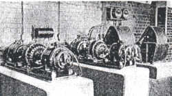
Fig 306 – Special Signalling Generators at Carnarvon Station.
disc discharger when it is disconnected from the main generator for as-synchronous working.
Photograph Fig. 307, gives a view of the high voltage transformers and primary inductances. All the current from the generators passes through the transformers, where it is stepped up to a voltage sufficient to charge the condensers. The low-frequency inductances shown to the right of the drawing permit a large range of adjustment in the primary power circuits, thereby permitting the radiated energy to be controlled in accordance with the requirements. Fig. 308 shows the switchboard at the New Brunswick, New Jersey, station. This board controls the generator circuits, blower machinery, and all-controlling appliances within the station. The receiving station at Belmar, New Jersey is completely equipped with a Marconi balanced crystal receiving set, Brown amplifying relays, a balancing out aerial for eliminating interference, dictaphone receivers, and a set of telegraphic instruments for connection with the landline telegraph and telephone companies. These transmitting and receiving stations not only have the necessary buildings for the housing of the apparatus, but hotels and individual dwellings are supplied for the employees as well.
| Stations separated about 30 miles |
Stations
separated about 30 miles |
At the writing of this volume, this group of stations is under construction and very nearly completed. They will be used for 24-hour commercial working and will permit communication with Northern European countries, independent of all existing routes, obviating the necessity for a number of intermediate relay points.
The transmitter at Marion will be a 150 K. W. Marconi timed-spark continuous wave generator, energized by a 300 K. W. 5,000 volt D. C. generator. The transmitter at Stavanger will be substantially a duplicate, with the ultimate capacity of 300 K. W. Since they have been found the most economical and practical for the purpose, the aerials at these stations are supported by tubular steel masts. As usual, the stations are constructed for Duplex working, Marion and Chatham as well as Stavanger and Naerboe stations, being connected together by landline control. These stations will be placed in commercial operation within a very short time.
| Stations separated about 40 miles |
Stations
separated about 25 miles |
| Stations separated about 60 miles |
Single Station
|
*Station is located at Hinna.
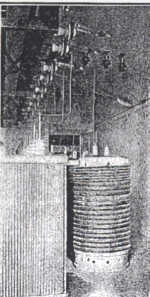
Fig. 307 – Bank of High Voltage Transformers at Carnarvon Station.
MARCONI TRANOCEANIC RADIO TELEGRAPHY 297
Because the transmitter at Kahuku is duplexed for simultaneous transmission to Japan and the U. S. A., the two circuits, No. 4 and No. 5, have been grouped together. Beginning with the Bolinas station, the transmitter is of 300 K. W. capacity, current for its operation being supplied by duplicate 500 H. P. steam. turbine-driven generators delivering current at 180 cycles per second. In the usual manner, this current is stepped up by closed core transformers to approximately 50;000 volts and employed to charge a bank of high voltage oil plate condensers. Although normally operated at from 75 to 150 K. W. the full 300 K. W. can be employed whenever necessary.
The aerial for receiving from Bolinas, Cal., is nearly a mile in length erected on two rows of tubular steel masts in the usual manner. The receiving aerial at Marshalls, California, has 7 masts, each of which is 330 feet in height.
The receiving station at Koko Head, Hawaiian Islands, has two distinct receiving aerials, together with balancing out aerials, one being employed! for reception from Bolinas, Calif., and the other from Funabashi, Japan.
298 PRACTICAL WIRELESS TELEGRAPHY
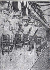
Fig. 308 – The Switchboard of the New Brunswick High Power Transoceanic Station.
The aerial for receiving from Bolinas extends southwestward from the operating house and is carried on five 330 feet masts to an anchorage on the beach. The aerial for reception from Japan extends from the operating room almost due east. The first two masts for this aerial are of the standard sectional type 430 feet in height; the first is on level ground and the second is on the hillside. From this point the aerial makes a long span of over 2,000 feet to the top edge of Koko Head (an extinct volcano) at an elevation of 1,194 feet above the sea level; here there is not enough room to erect a sectional mast, only about 40 square feet being available for a self-supporting structural tower 150 feet in height. The tail end anchorage for this aerial is far down the volcano on the inside of the crater. The balancing aerial,-which is employed for both receiving aerials, is erected on self-supporting towers; each of which is 100 feet high. All this will be clear from the diagram, Fig. 309, wherein a complete layout of the receiving station at Koko Head appears showing the relative positions of the balancing out aerial, the location of buildings, etc. It is to be noted that the balancing out aerial is 5,700 feet in length, and is arranged to be favorable for the absorption of energy from the two transmitting stations at Kahuku.
Because it is duplexed for the simultaneous transmission of messages to Japan and the United States, special interest attaches to the Marconi station at Kahuku, Island of Oahu, Hawaiian Islands. Not only is this station fitted with two 300 kilowatt transmitting sets but a third emergency set has- been installed as well, which in event of breakdown can be connected either to Japan or the United States aerial.
The general layout of the antenna; and buildings at Kahuku is shown in the diagram, Fig. 310, wherein it will be noted that the free end of these aerials point in a direction
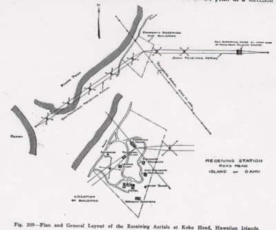 Fig. 309-Plan and General Layout of the Receiving Aerfavorable for the particular continent with which communication is to be established, being designated as the “Japan” aerial and the “San Francisco” aerial From the powerhouse as a center, the California transmitting aerial extends southwest-ward, supported by twelve masts, 325 feet in height; the Japan aerial extends to the south-east, supported by fourteen masts, 475 feet in height. These masts are the largest that have been yet constructed on the Marconi system of sectional cylinders. The powerhouse consists of boiler room, engine room, and condenser room. The boilers are oil-fired and will feed three 500 H. P. turbines, which drive the special 300 K. W. alternators and Marconi disc discharger.
The necessary condenser capacity for all three transmitting sets is found in 768 large oil tank-type condensers, which are conveniently arranged for uniform distribution of current to all connecting bus bars.
The automatic sending and receiving apparatus plays an important part in the service between the Occident and the Orient. The sending machine consists of a Wheatstone automatic transmitter and special perforator, which makes possible the transmission of more
MARCONI TRANOCEANIC RADIO TELEGRAPHY 299
than 100 words a minute. Under the automatic system, ten or 100 messages can be filed at the same time at the office of the Marconi Company in Honolulu. They will be distributed among the necessary number of operators and the dots and dashes punched in a paper tape by a typewriter perforator. This tape is fed into an automatic sender and the signals conveyed by landline to Kahuku, where the dots and dashes actuate a high voltage sending key, automatically energizing the aerial instantaneously with the feeding of the tape in the station, thirty miles or more away. At the transmitting station, the dots and dashes operate the magnets of the high power sending key in the main energy circuits and the signals are
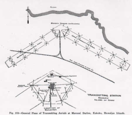
Fig. 310-General Plans of Transmitting Aerials at Marconi Station, Kahuku, Hawaiian Islands.
flashed to whichever destination the message calls for-either Marshalls or Funabashi. If the message is destined for Marshalls it will be received on a specially constructed dictaphone machine, each cylinder, as soon as it is indented with dots and dashes, being handed to an operator, who transcribes it into a typewritten message by means of a reproducing dictaphone machine, running at normal speed.
The Imperial Japanese Government station at Funabashi, Japan, is equipped with a 200 K.. W. quenched spark transmitter, but complete details of the equipment are not yet available
235. Marconi Tubular Masts.-One of the most interesting features of the original construction work at the Marconi high power stations was the erection of the steel tubular masts, the successive stages of erection being shown in Figs. 311, 312, 313, 314, and. 315. The mast is made up of steel cylinders (Fig. 311), constructed in quarter sections, flanged vertically and horizontally, and secured together by bolts stayed with steel cables. This ‘ stand in ‘a concrete foundation. Surmounting the main steel column was a wooden topmast, the lower part of which is squared and get in square openings in the plates between
300 PRACTICAL WIRELESS TELEGRAPHY
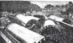
Fig. 311 – Showing Steel Semi-Cylinders for the Marconi
Tubular Mast.
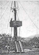
Fig. 312 – Showing Workmen’s Cage Which is Carried to the Top During the Process of Erection.
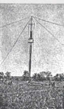
Fig. 313 – A Tubular Mast in Early Stages of Construction.
the steel cylinders. The hoisting arms attached to the upper end were fitted with blocks and hoisting cables. Attached to these arms were chain hoists supporting a square wooden cage (Fig. 312) for the workmen, which was lowered or raised as the demands of the work required while the sections were being bolted together.
The wooden topmast was the keynote of this novel system of construction, operating like a man who pulls himself up by his boot-straps. The lower half of this topmast is of square section and is guided by a square hole in the diaphragm plates between each section. The topmast was fitted with a set of hoisting arms that carried blocks through which revved the material hoisting ropes. A square wooden cage was suspended from the hoisting arms by four chain hoists so that the workmen in it could move up and down to bolt the sections together. This is more clearly shown in Fig. 314.
Assume that two cylinders have been bolted to the bedplate, the mast rising through the center. The sections of the third cylinder were raised by a steam winch and bolted in place by the workmen. Then a heavy flexible steel rope was temporarily anchored at the top of this last cylinder. Attached to the top of the steel section, this cable led down inside the cylinders and around a wheel in the foot of the wooden topmast; then it was carried up again on the other side and around a sheave to the top of the steel, thence to the winch. By pulling on this rope the topmast has raised the length of one cylinder and pinned through holes in both steel and wooden masts. With the addition of a new cylinder, the topmast was raised again, the pin supporting it until this was brought about (Fig. 313). The stays were attached at the required points as the erection of the mast progressed.
The stays, by means of which each mast is supported, Fig 312-Showing Workmen’s Cage are made of heavy plow steel cable, possessing great Which is Carried to the Top tensile strength. For each mast thousands of feet of this
During the Process of Erection. cable wire used, great care being taken to see that the elastic extension of these stays was not so great as to result in the vibration of the mast during heavy winds. It was essential to break each stay into short lengths connected with great porcelain insulators in order that the electrical energy might not be absorbed, led to the earth by the stays, and lost for purpose of wireless operation. For all connections at the masts, insulators, and anchorages, special bridge sockets were designed. This did away with the necessity for splicing and permitted a perfect and straight-pull, thereby developing the strength of the cable. Heavy concrete blocks were used as anchorages for the stays. The completed mast is shown in Fig. 315.
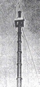
Fig. 314 – Showing the Cage and the Top Mast Several Hundred Feet from Earth.

Fig. 315 – Completed Mast (Guys Not Shown)
In addition to the antennae stretched between the masts, great quantities of wire were placed in the ground about the stations in order to provide an efficient earthing system or ground connection. Told in brief, a circle of zinc plates is buried in a trench, bolted together, and jointed to the wireless circuits of the powerhouse by copper wires. Wires radiate from the zinc plates in the ground to a set of outer plates, from which extend another set of earth wires placed in trenches running the full length of the aerial. The general scheme for the earth connection is shown in Fig. 320.
Page created December 30, 2000
There are no upcoming events at this time
We Need Your Help! Volunteer with Us.
Join our mission to preserve historic Camp Evans and teach the public about science and history.
Sign up to join our team of volunteers and start on your own mission today.
InfoAge Science & History Museums
2201 Marconi Road
Wall, NJ 07719
Tel: 732-280-3000
info@infoage.org
webmaster@infoage.org